Electronics, Inspiring, Machine learning, Uncategorized

Avoid touching face using a low-cost fitness tracker

final_5e9488d7458d7f00159c3b84_233455In addition to washing hands regularly and social distance measures, avoiding touching our face is one of the advice given to prevent the virus from entering our body. It is well known that Corona virus enters our body mainly through the nose, eyes and mouth.

However, it is difficult to follow the advice and we touch our face unconsciously many times a day. Since the Coronavirus can stay alive for more than 3 days on many surfaces, it is a good suggestion to avoid touching our face. This is even more true in the case of healthcare professionals, who are working for us in highly dangerous conditions.

There are some companies ( Immutouch and Shockbit) that are marketing these smart bands that alert users when they are about to touch your face.

Truth is that almost all the existing fitness trackers can alert you when we are about to touch the face. This is very similar to showing the time automatically when you twist the wrist. For this we don’t need to buy a new fitness tracker or a smart band.

However, this feature is not activated in regular fitness trackers but it is not difficult to implement.for excrumple, Many fitnesstraces homecantelltimeWhen gonertwist yourholdto seethetime.All we need is to take the data from the accelerometer and detect when a user tilts his hand more than 30 degrees. In that case the fitness tracker alerts the user by vibrating the motor inside the fitness tracker.

How can we detect the tilt of hand from accelerometer data that usually gives acceleration in x,y,z directions? Turns out that one can measure the tilt angle using just the acceleration in the x, y, z axis from the below equation.

Scientists from MIT media lab used the above equation (only used Ax value) and uploaded their custom firmware into a low-cost (~$10) fitness tracker. Fortunately, all this is open source, so thanks to the team. More importantly this is all done Using

Since I have the same exact fitness tracker It is easy for me to test the Code immediately. The fitness trader is DG the code was Originally efforts of atelll and famoush actilly actually made a simple app for flashing the custom firmware easily. In the following I will explain howto achieve this willt the given fitness tracker.Arduino, so that it is easy to understand and modify.

I uploaded their code into a DS-D6 fitness tracker and found a small bug. This code doesn’t work if the screen is active with any other function running. This is because the MIT media lab has just added this face touch alert system as an extra function to Aaron’s (and Fanosh’s) code written for hacking DS-D6 fitness trackers. Original Aaron’s code has many features such as showing time, playing sandbox games etc.

That means to alert the user when he/she is about to touch the face, the fitness tracker should be in a particular mode. I found that it is inconvenient and sometimes, the fitness tracker is going to other modes (such as showing time or showing default messages etc) due to accidental touches on the fitness tracker’s screen. Therefore, I removed all the functions of the MIT media lab’s code and kept only the “not-touch-face” function. Now it is working without any issue and as a bonus the fitness tracker’s battery performance has also improved. Please see the video here and the code here. I am working on this particular alert feature to work along with all other features, so that I don’t need to delete them.

Apart from the DS-D6 fitness tracker, the code should work with any of the following fitness trackers: Mpow DS-D9/Lenovo HW02, Lenovo HX03W. Most of these fitness trackers cost from $10 to $20 in ebay/Amazon/Aliexpress. I hope most of the mainstream fitness tracker companies such as Apple and Fitbit will give this as a standard feature in the future, so that we don’t need to buy new smart bands for this one feature.

Instructions to make your own face touch alert system

  1. Buy anyone of the above described fitness trackers.
  2. Upload the fitness tracker first with this simple bootloader code.
  3. You need this app to upload the above bootloader. Please watch this video on how to flash the bootloader.
  4. Upload my code into the fitness tracker using the same app in the same way bootloader is uploaded.


P.S1: It will be cool if we can achieve this with Tiny ML, I hope someone does that.

P.S2: There is a very simple DIY way of achieving this “avoid touching face” function without using any of the smartness of a fitness tracker. Another DIY approach is to use off-of-the-shelf circuit board, but the code of this approach doesn’t look great.

Acknowledgements

Sandeep Mistry, fanoush, atc1441 and MIT media lab.

Standard
3d printing, DIY, Electronics, Robotics

ElectroMagnetic Probe for DNA Isolation

Use of Magnetic probe in wet lab biology

Magnetic beads are widely used in wet lab biology to purify molecules such as DNA, RNA and proteins from solutions. Magnetic beads are used to selectively attract the molecules of interest from a mixture of enzymes. This is very common in various life science research settings. The ability to artificially create DNA (Synthetic) has significantly transformed the field of biomedical sciences. Various applications in medicine, food and materials technology have opened up and resulted in establishment of industries and research facilities that use synthetic DNA on a day-to-day basis.

During DNA synthesis, the strand separation post-dsDNA synthesis and the extraction of single stranded DNA from a pool of enzymes are key steps. Usage of paramagnetic beads that selectively bind to modified DNA base pairs of a single strand, is an attractive option for this purpose (see Fig. 1). This is done by heating the reaction-well (≥ 65°C) to denature the DNA strands, leading one strand available to attach to the paramagnetic beads and the other strand freely floating in the solution. At this point, a magnetic probe is used to isolate the magnetic beads (which have the attached ssDNA). As a result ssDNA is successfully isolated and the next steps are carried out.

Figure 1: Magnetic bead separation using a magnetic probe. a) Single strand DNA molecules are attached to magnetic beads b) A magnetic probe is lowered into the solution and magnetic beads (along with the DNA molecules) are magnetically attached at the bottom of a magnetic probe c) Magnetic probe brings the beads (along with the DNA) into a new solution d) A permanent magnet near the tube will release the magnetic beads back into the new solution e) Finally magnetic probe is removed from the solution.

Why using a permanent magnetic probe is not a viable solution for high-throughput applications.

This isolation process can be scaled up for high throughput DNA synthesis by equipping a robotic handler (ex: OpenTrons) with a magnetic probe device. Permanent magnetic probes exist in the market to extract the magnetic beads after the denaturation process. However, the harsh environment of the DNA synthesis process (which involves multiple heating and cooling cycles) introduces hysteresis and permanent magnet slowly loses its magnetic property. Moreover, it is also very difficult to find permanent magnets that can fit the standard disposable pipette tips. Therefore, we were contacted by a start-up company to design a special magnetic probe for isolation of DNA

Design and fabrication of magnetic probe

To overcome the hysteresis problems of a permanent magnetic, we would like to make a magnetic probe that exploits electromagnetism (EM). The advantage of the EM probe is that it can be with a customised shape to fit to standard disposable pipette tip. The basic design of the Magnetic Probe is given by the start-up company.

The design of the EM probe started with a copper coil harvested from a relay switch. For the initial testing, we kept a nail as the core of the electromagnet (Fig. 2a). We simply applied 5 volts and the probe started to attract the iron dust (see the video here https://www.youtube.com/watch?v=HlXHz4GMDSs). When the prototype was working, we designed a holder using OpenScad (Fig. 2b). Surprisingly, it took us more time to design the holder that can hold the copper coil in place. In the initial prototype we used a nail as the core for the EM probe (Fig. 2c). We used a knitting needle as the core of the EM probe. Dimensions of this needle perfectly matched to use with disposable pipette tips (Fig. 2d).

Figure 2: a) Prototype of an EM probe made with a Copper-coil harvested from a relay switch b) CAD diagram of the EM probe holder c) First Assembled EM probe d) Final assembled EM probe.

Future scope

In the future, we would like to mount this magnetic probe on an Opentron liquid handling robot and validate the whole device with a few DNA samples. The same process could be extended towards RNA and protein isolation as well.

Acknowledgements

Nimesh, Vamsi, Uday and SMART – Servier Medical ART

Standard
DIY, Electronics, Inspiring, LEDs, Machine learning, Uncategorized

DIY Smartphone Spectrometer part 1

What is a spectrometer

Many of us might have witnessed a beautiful rainbow during a rainy day. Rainbow is basically a spectra of light. Rainbow is formed when sunlight is dispersed into several colours by rain drops. If we can make an instrument that can do the same job as the rain drops do i.e. disperse light into its constituent colours, that instrument will be called a (optical) spectrometer. Spectrometer is also called a spectrophotometer, spectrograph or spectroscope.

Usually a prism or a grating is employed in spectrometers to disperse light. The other essential components of a spectrometer are a slit and a spectral recording medium to store the spectra for analysis. Of course scientific spectrometers consist of more than these bare minimum components. Spectrometers are used in many applications, including environmental, medical, bio, chemical and gems analysis. Several types of spectrometers have been developed for various applications. Here, we discuss spectrometers that work in the visible spectral region, i.e the spectra what we can see with our eyes.

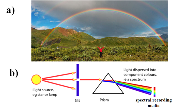
Figure 1: a) Rainbow (spectra) formed by rain drops (PC: wikipedia) b) A simple schematic of spectrometer with most essential components indicated. (P.C AglsAgent et al. )

Why smartphones are interesting for spectroscopy

As mentioned earlier, a bare spectrometer requires a slit, light dispersing element, spectral recording medium. In scientific spectrometers, the light recording medium is usually a special camera with very cool features such as high resolution, low-noise and high quantum efficiency. Apparently, cameras in smartphones are used for recording the spectra. These days cameras in spectrometers are ever evolving with 100’s of megapixels and have quantum efficiencies rivaling the performance of high-end scientific cameras. Therefore, smartphone cameras can be exploited to turn a smartphone into a spectrometer.

Another great feature of smartphones is the touch screen that can act as a great user interface for a spectrometer by providing instant access to recorded spectra. Smartphones also provide connectivity options such as Bluetooth, WiFi, Mobile network for transfer of recorded spectra. Therefore, smartphone cameras are highly attractive to be used in research.

How to turn a smartphone into a spectrometer

Since one of the three components of a spectrometer, i.e. spectra recording medium is provided by smartphone, one needs to add just a slit and a light dispersing element to turn a smartphone into a spectrometer. There are many smart people and research groups that are trying to add these basic optical systems to a smartphone, primarily by using the emerging digital fabrication tools such as 3D printing, laser cutting or paper cutting.

I have been following this smartphone spectroscopy field for a very long time. I am inspired by the available smartphone spectrometer designs. I would like to make spectrometer designs that are simple, low-cost, DIY friendly, or designs that can be made with off-the-shelf components and require fewer 3D printed parts.

I hope such smartphone spectrometers will be useful for many applications such as point of care diagnosis, analysis of biomedical fluids, chemical analysis in research labs and as a great teaching tool for school children.

Smartphone spectrometers that inspired me

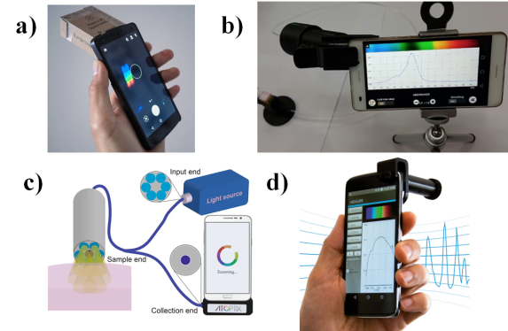
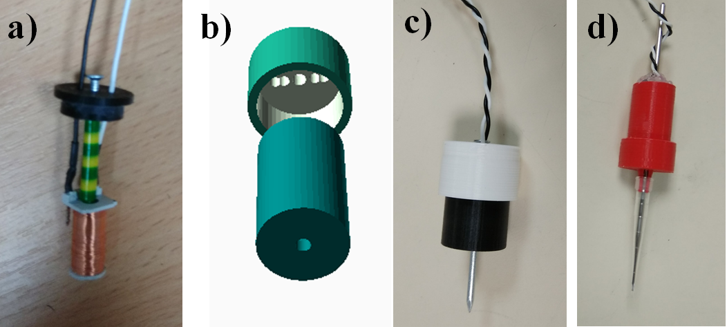
Figure 2: Various smartphone spectrometer designs a) Public lab’s paper craft spectrometer b) Spectrometer made using the lens from google cardboard project c) Spectrometer with fiber integration d) Commercially available smartphone spectrometer.

I am inspired mainly by 4 designs which I show in Fig 2. The very first one (Fig 2. a) is from Public lab’s DIY spectrometer. Several models of excellent spectrometers were demonstrated by the members of this awesome community. Out of their many designs, my personal favourite is the Papercraft spectrometer which is an evolved version of their Foldable Spectrometry Starter Kit [1]. These designs are easy to be made using just a few components i.e. a thick paper sheet, a grating made from a DVD disk. Their software is mainly web based (it can be installed on Windows and Linux, but not easy). I used the software sparsely but I am not a huge fan of it.

I made this spectrometer using a cardboard sheet and a fragment of a DVD. The initial spectra recorded from light emitting sources such as CFL lamps and Tungsten bulbs are fun. But the above designs don’t have provision for absorption and fluorescence spectra as they simply don’t have sample holders and light sources.

My second favourite (Fig. 2b) is the one made by researchers from Universidad Privada Boliviana. The impressive thing about this spectrometer is the smartphone app they developed. Although I never built their version of the spectrometer, I used their app extensively. I really like their app which was developed using OpenCV. I wish they also open sourced their source files of the app. The highlight about their hardware set-up is that they used commercially available lenses originally intended to be used for google cardboard projects.

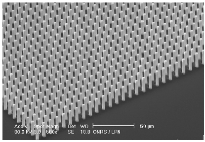
My third favourite (Fig. 2c) is the one that employs an exotic fresnel lens fabricated using photolithography. So I am not going to make this version of spectrometer, but I like their application to use the spectrometer as a fiber probe. Most of the published literature on smartphone spectrometer has

Finally, the one I like is a commercially available GoSpectro. Their design looks very simple and their suggested application i.e color measurements of lights seems where first deployment of smartphone spectrometers makes sense. But the cost of the spectrometer ($450) doesn’t make sense given the hardware cost of the device is a few dollars. Moreover their spectrometer design works with only a few smartphones .

What features I want in my spectrometer design

  1. Plug and Play Modules: I would like to develop different smartphone spectrometer modules for different applications. All these modules will be built on top of a simple base design. Changing between different modules of the spectrometer should be plug and play.
  2. Integrated light source: I don’t want to use the inbuilt LED of the smartphone. Instead, I developed a small external LED light. This helps to have a consistent light source across all smartphones. It doesn’t drain the smartphone’s battery. Using a smartphone’s flash for recording the spectra is not very convenient, at least in my experience.
  3. Rechargeable battery for the LED: It helps to have a compact rechargeable battery that makes it easy to use the spectrometer, without worrying about replacing batteries.
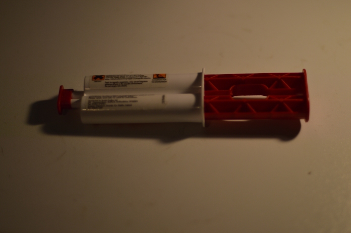
  4. Dispersing element: I used an off-the-shelf jewelry spectrometer that has a grating, slit, lens all in one package. So it is easy to replicate by others without worrying about the optical alignment, awkward slit width problems. Also, this design helps to keep the spectrometer straight against the camera, that way it is convenient to use, also looks neat.
  5. Software: I am developing a software that will make use of OpenCV and other machine learning techniques.
  6. Fewer parts: My design should require fewer 3D printed parts. For example, the simplest module requires only a single 3D print attachment and the more complex module requires only 3 parts and none of them require any extra processing such as gluing.

My early prototypes of smartphone spectrometer

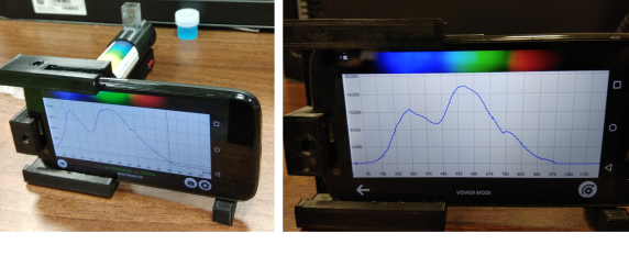
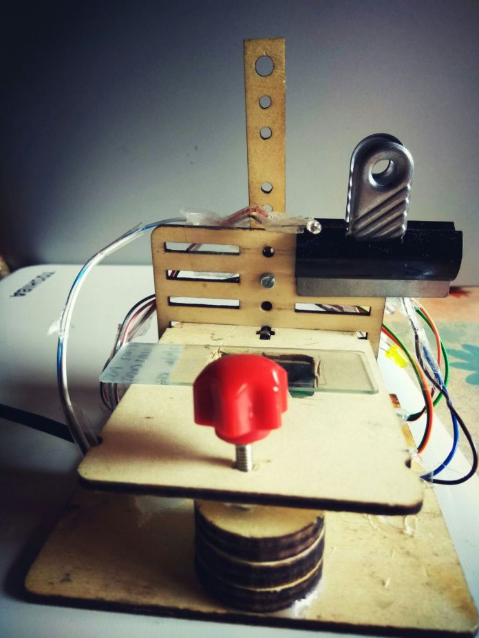
Figure 3: Left: Early prototype of my smartphone spectrometer. Right: Spectra recorder using the app from Universidad Privada Boliviana.

My very first prototype of smartphone attachment is based on Jeweler’s spectrometer tube that is of the size of 15cms. The attachment used to feel very heavy (~100 to 150gms). Handling this spectrometer doesn’t feel really convenient. The prototypes are shown in Fig 3.

Then, I found a smaller Jewelry spectrometer that is really 1/3rd of the size of the original spectrometer tube. It simplified my design of the spectrometer as shown in Fig. 4. I struggled a lot to make the rechargeable LED light for this spectrometer. At the beginning, it seemed easy, but I had to make several prints to make it right. Software proved to not be a nice experience. The existing apps are neither open source nor easy to use. I might be missing a good app or such an app never existed I might be missing a good app or such an app never existed (Let me know in the comments, if you know any good one). In part 2 of this post, I will share more details with pics of the new build, instructions and a few measurements.

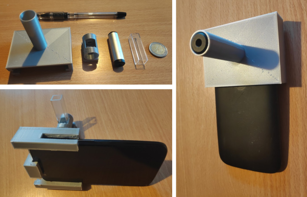
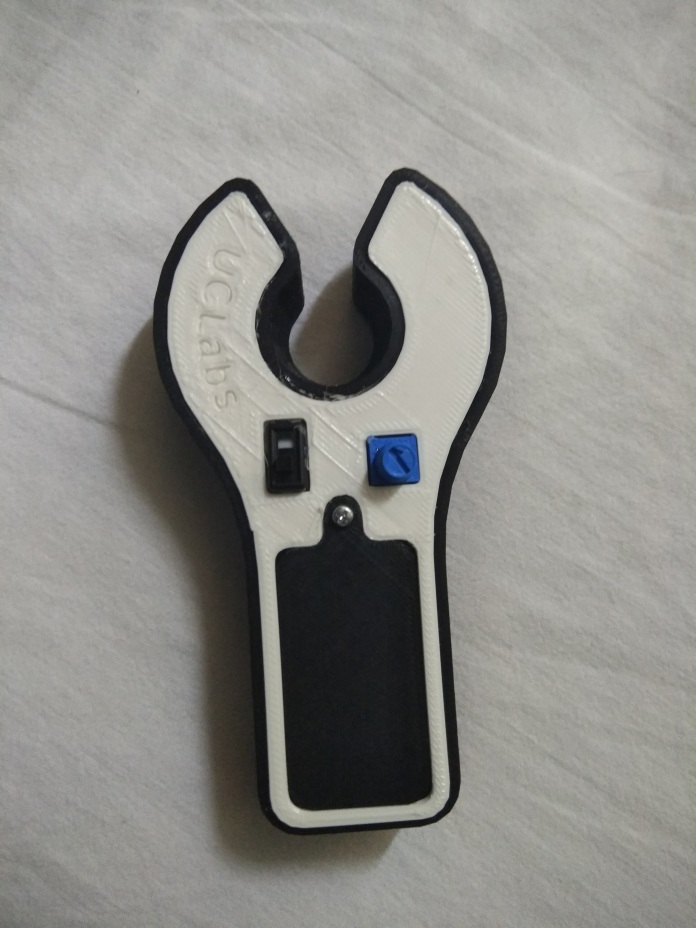
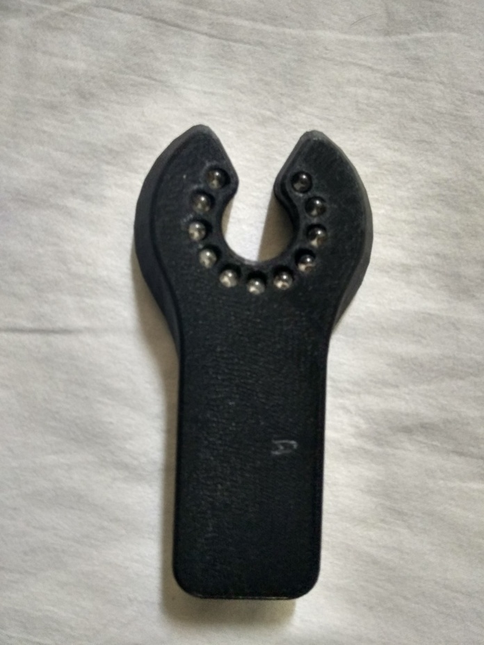
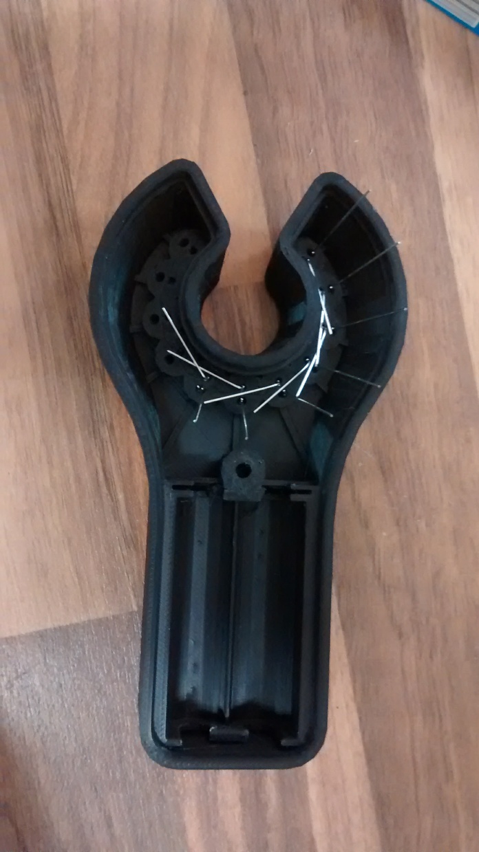
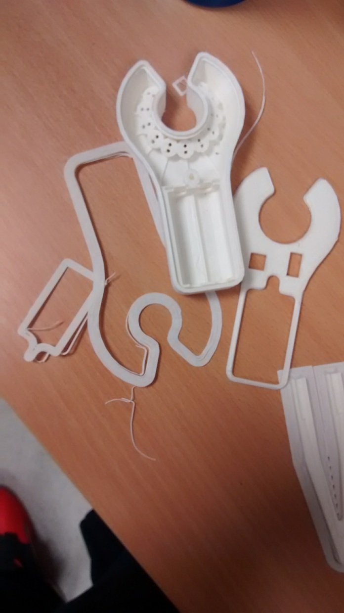
Figure 4: Top Left: 3D printed parts for the smartphone spectrometer before the assembly. Coin is there to show how small the spectrometer attachment is. Right: Assembled spectrometer with Jeweler’s spectrometer tube inside the 3D printed attachment. Bottom Left: Completed assembly with sample holder and cuvette in place.

References

  1. https://publiclab.org/wiki/foldable-spec
  2. http://www.gaudi.ch/GaudiLabs/?page_id=825
  3. https://publiclab.org/wiki/oil-testing-kit
  4. https://www.thingiverse.com/thing:125428
  5. https://www.goyalab.com/product/hand-spectrometro-gospectro/
  6. https://www.nature.com/articles/s41598-017-12482-5?utm_source=other_website&utm_medium=display&utm_content=leaderboard&utm_campaign=JRCN_2_LW_X-moldailyfeed
  7. https://www.spiedigitallibrary.org/conference-proceedings-of-spie/10657/1065702/Smartphone-spectroscopy-for-mobile-health-diagnostics-with-laboratory-equivalent-capabilities/10.1117/12.2303609.short?SSO=1
  8. https://www.researchgate.net/publication/274964166_Combined_dual_absorption_and_fluorescence_smartphone_spectrometers/figures?lo=1
  9. https://www.upb.edu/en/contenido/spectrometry-software-for-android
  10. https://pubs.rsc.org/en/content/articlelanding/2016/lc/c5lc01226k#!divAbstract
  11. https://www.youtube.com/watch?v=BTN00-6Lh5Q
  12. https://www.consumerphysics.com/order-scio/?mnsid=mrmobile
  1. http://lightingpassporttestdom.weebly.com/contact.html
  2. https://www.intechopen.com/online-first/from-sophisticated-analysis-to-colorimetric-determination-smartphone-spectrometers-and-colorimetry/
  3. https://link.springer.com/chapter/10.1007/978-3-030-02095-8_4
  4. https://www.laserfocusworld.com/test-measurement/spectroscopy/article/16571436/wave-illumination-handheld-spectrometer-offers-3-nm-fwhm-optical-resolution
  5. https://www.shapeways.com/product/Z6HDKHSTL/coffee-spectrometer-housing?li=productGroup&optionId=11925870
  6. Rateni, G., Dario, P., & Cavallo, F. (2017). Smartphone-based food diagnostic technologies: A review. Sensors (Switzerland), 17(6). https://doi.org/10.3390/s17061453
  7. https://www.researchgate.net/publication/274964166_Combined_dual_absorption_and_fluorescence_smartphone_spectrometers
  8. https://phys.org/news/2015-07-smartphone-day-youre-pregnant.html
  9. https://www.sciencedirect.com/science/article/pii/S0003267019311729
  10. https://www.spiedigitallibrary.org/journals/journal-of-biomedical-optics/volume-23/issue-04/047003/Real-time-biodetection-using-a-smartphone-based-dual-color-surface/10.1117/1.JBO.23.4.047003.full
Standard
Inspiring, Machine learning, Thesis writing, Uncategorized

ESGI – A Different Type of Conference

Recently, I have attended 141th European Study Group with Industry (ESGI) conference in Dublin. It is a very different type of conference/workshop than what I have been attending so far. First of all everything is free, including food, coffee, snacks accommodation and registration – thanks to funding bodies SFI, UCD, MI-NET, MACSI. Second, it is a great opportunity to meet experts from different fields. Third, there are not so many talks or hurried people and most people are young post graduates and post-docs rather than professors. Everyone is there to learn rather than to advertise their work. More importantly, everything ran smoothly till the end of the conference.

The theme of the conference is that industries across Europe pose 5-6 challenges and 50-100 researchers from EU will solve these challenges in 5 days. It is something like a hackathon. This year, most of the problems from the industry are data science related. Since data science/machine learning is a hot topic, many people opted for these challenges. I opted for a Physics related challenge, that is related to wetting/wicking of rough surfaces. A semiconductor company has been looking for an optimised rough surface that can be wetted as easily as possible.

micropillars1

Wicking of Surfaces Decorated with Microplillars [1]

Although it seems simple at first glance, it is important to stress that by roughing a surface, wetting can be enhanced many orders of magnitude. For example, if we leave a water drop on a flat surface it takes up to 10 days to spread a diameter of 2cm. While using a optimised rough surface it takes only 10s. Such fast wetting of surfaces has applications in biomedical sensors where for example blood or urine samples can be reached to sensing regions easily.

This problem is interesting as it brought me back into the basics of physics, mainly fluid dynamics. Along with me, there are 13 members who liked this Physics challenge. So we formed as team that consists of 2 professors from Oxford. In the end only 5-6 people remained interested in the project and the rest slowly drifted away. Within our team, we formed sub teams, according to the level of expertise. I worked on my own as I don’t have any particular expertise in fluid dynamics.

Problems were given before we were going to the conference, so I did some back ground reading. In the first day itself, I met the company representative from the semiconductor company who gave this challenge. I expressed my interest to him. I read as many as 20 papers on this topic and came to a conclusion that the most of the things that the company would like to know about wetting of a rough surface were already studied/solved.

So I took the second day completely to read more literature and to make sense of it. On the third day, I narrowed down on 5-6 good papers and analysed them deeply. According to these papers, my conclusions are as following:

1) Critical angle of a drop on a rough surface depends on the roughness and it will be different than the critical angle on a flat surface.

2) The roughness dictates whether a surface can be superhydrophilc or superhydrophobic

3) Most rough surfaces studies are silicon cylindrical pillars on silicon substrate.

4) Dynamics of liquid spreading on a superhydrophilic rough surfaces follows washburn’s law i.e. the penetration length of the liquid front is proportional to the square root of time.

5) One can optimise the geometrical parameters such as height and diameters of the pillars and periodicity between the pillars to achieve faster spreading of a liquid drop on a rough surface.

Overall, we presented our findings. I made some friends. I enjoyed dwelling into other scientific field. I hope these type informal conferences will happen more frequently. I highly recommend my fellow researchers to attend the future ESGI conferences. I am looking forward to attend the next ESGI workshop.

References

Ishino, C., Reyssat, M., Reyssat, E., Okumura, K., & Quéré, D. (2007). Wicking within forests of micropillars. Epl, 79(5), 6–11.

Standard
3d printing, DIY, Inspiring, Robotics

Use of 3D printing in science labs

IMG-20180313-WA0000

First 3D printed prototype without guide rails

IMG-20171204-WA0001

Final 3D-printed tip box holder tray with guide rails and springs to tightly hold the tip boxes in place

IMG-20171204-WA0003

3D printed tip box holder with tip box in place

IMG-20171204-WA0006

Our 3D printed tip holder with Andrew Robot

Andrew Alliance’s Andrew, is an impressive little automatic liquid handling robot. For example, my friend who works in a cancer research lab, uses it extensively in his everyday wet lab experiments. One of the problems associated with these sophisticated robots is that they have a very high cost for their accessories. In Andrew’s case, it uses a spring loaded tray to hold a PCR tube/ tip holder box. This tray doesn’t have to do anything other than holding the box in its place firmly. The company priced it over 300£ which is not well justified. If there is anything that is a bit complicated, is the tray that uses the tension of the spring to hold the box in its position. That’s is all about it. It has no electronic component or anything that could push the price over £10, still these companies price it for over £300. Don’t forget the VAT, import taxes, shipping time and costs involved. 3D printer. These reasons lighted up a solution for us here. We’ve decided to 3D print the holder and fix a spring to it. It took me no more than 2 iterations and now we are flying. While it took a little more time than expected to get the spring to function properly. However, I found what I needed in a knit shop- a small railing that need to hold the spring axially. That’s it and the holder is now in my friend’s lab, doing what it is supposed to do, hold the box in its position. It’s funny how such things are so simple and still these companies price them so high. However, with the advent of DIY 3D printers our jobs are getting simpler, reducing the time and costs involved.

What I’ve learned from this little experience is that, many such accessories, like the Andrew’s tip box holder in this case, once we know how to 3D print and design a few simple designs we could make as many of them as possible. We were able to make 3 holders for less than $30 and in no time. 3D printer made this look a kids play project. This little example, shows a perfect use of 3D printers in scientific labs or for printing DIY stuff for your own daily needs.

Credits: Vamsi, for throwing the problem and providing the feedback. Uday, for his help with fixing the rails and springs


Standard
DIY, Electronics, Inspiring, LEDs, Lux, Robotics

DIY Vein viewing Device

The problem with veins:

I afraid of getting injections with syringes as it is a very painful experience. Unfortunately, for some people it is even more painful, if their veins are not clearly visible. In that case, usually nurses try to insert the needles into the body by guessing the vein’s position. Sometimes after three to four trails they have to change the spot and start to probe again for invisible veins. It’s particularly a problem for new born babies. Witnessing that needle punches itself is a painful experience.

Simple Solution:

One of the simplest solution to this problem is illuminating the veins by powerful LEDs. This solution relies on the fact that there is a change in colour of the blood, depending on whether it is carrying the oxygen or not. This change can be easily noticeable when veins are illuminated with red LEDs. By exploiting this fact, a company called veinlite made a device that consists of just LEDs (red and orange) and a battery to power them. It has been proved that this device works but it gets patented thus it costs $200 to $300. There are clones of this device, but they too cost ~$100, so these are not particularly affordable to most hospitals.

Open source version:

However, there is a nice guy called Alex, who made a open source version of veinlite and kindly shared the design files with instructions. Recently, I come across a friend who is suffering from this not so easily visible vein’s problem. Therefore, my friend’s hand was swollen and it’s really painful. So I attempted to build this vein viewer with the help of Uday. We just made a one small change to the original design of Alex, by adding a small potentiometer to adjust the brightness of the LEDs. Below are the few pics showing the build process and initial tests. I hope this will be useful to my friend. We didn’t have the exact switch used by Alex, so we adjusted the hole for the switch in the design accordingly. In the future, we will try the rechargeable battery version, if we find the cause. Please see the videos below to know, how it works.

IMG_20170816_101037

Top View of our 3D printed VeinViewer

IMG_20170816_101112_HDR

Bottom View of our 3D printed Vein Viewer

IMG_20170812_194006857

Vein Viewer during the soldering phase

IMG_20170812_220525185

First version printed with a wrong colour of a material.

References:

http://www.instructables.com/id/3d-Printed-Medical-Vein-Finder/

http://www.instructables.com/id/How-to-make-an-affordable-Vein-Finder-for-use-d/

https://3dprint.com/11056/3d-printed-vein-finders/


Standard
DIY, Electronics, Inspiring, LEDs, photography

Webcam DIY Microscope

I have a fascination with DIY microscopes. I have been making microscopes with ball lens and laser pointer lens etc. When these lenses are coupled with the powerful smartphone cameras, they produce highly magnified images of microscopic objects. However, I come across a very interesting webcam microscope through Guadi labs. Basically, when we reverse the lens of the webcam it acts as a microscope. There are many versions of this microscope in the Gaudi labs website, from which I chose the laser cut version for its simplicity. The parts were cut in 2016 when I was in St Andrews, but now only they are assembled as I kept this project in cold due to other interesting projects. The only improvement, I have done is connecting LEDS of different colours to the webcam board in place if its original white LEDS. That way I am planning to excite many fluorescent proteins.

microscope

Webcam Microscope front view


Below you can find the microscopic images of cells (~ 30um in length) taken with this webcam microscope. I also took microscopic images taken from smartphone based microscope with laser pointer lens (details will be in another post, see reference 2). Clearly, webcam gives large magnification but small field of view. On the other hand, laser pointer lens gives smaller magnification and large field of view. So these two DIY low cost systems can be handy for biological applications. In fact, I am making one of this microscope for my colleague to quickly screen drug injected cancer cells to know whether the drug has reached inside the cells or not. I will follow up the progress of that project in a future post. I must tell you that these microscopes are far better than the $15 usb microscope attachments that can be bought online.

WIN_20170621_065128

Microscopic image of cancer cells taken with webcam microcope under white LED illumination. The slide was stained with a blue dye.

Cells with orange illumination

Microscopic image of cancer cells taken with webcam microcope under orange LED illumination.

WIN_20170621_070323

Microscopic image of cancer cells taken with webcam microcope under red LED illumination.

IMG_20170621_072008081_HDR

Microscopic image of cancer cells taken with smartphone based microscope with laser pointer lens under white LED illumination.


References:

http://hackteria.org/wiki/index.php/DIY_microscopy

http://www.instructables.com/id/10-Smartphone-to-digital-microscope-conversion/

Acknowledgments:

Dundee Makerspace

Vamsi

Uday

Standard
ARDUINO, DIY, Electronics, Inspiring, LEDs, photography, Raspberry Pi, Robotics

Experiments with a Light Meter

Why I am interested in Light meters?

When I was working in Scotland, I came across photo dynamic therapy (PDT), which uses light sensitive drugs to kill cancer cells. In the entire UK, there are only two PDT centers (afaik), one of which is in Dundee. By visiting the PDT center in Dundee, I realised that after applying the PDT drugs, doctors ask patients to wait in  sun light for two hours. There is no particular reason for exactly two hours of exposure to sun light. Therefore, it is not possible to know how much light dose has been received by the patients. To address this problem, PDT center at Dundee measured sunlight across the UK and Ireland and suggested that  cheap lux meters can be used to measure the required lux dose. I met with one of the PI and discussed about this in detail.

The problem with cheap light meters:

However, most commercially available cheap lux meters can only give instantaneous measure of light. These are originally developed for photographers to know lighting in their photo and building mangers to know lighting in a room. But PDT application  requires the lux values to be logged, aggregated to know whether the required light dose is reached. I think the only way to realise that is through connecting the lux meters to a microcontroller and stream the values to a smartphone. For that I am going to use a cheap lux meter that I can confidently modify after reading this blog post .

What I did:

I ordered the lux meter with a brand name “Ceto”from the same vendor as suggested in the blog post mentioned above. I identified the pins required to tap to get the lux values out. These are the pins on the amplifier. I soldered wires to these pins to read the voltage. So effectively LUX values are converted to voltage values in this lux meter. For example LUX of 290 is converted as 0.288V. I connected these wires to a multimeter to  see these voltage values.

IMG_20160722_234716581_HDR

Guts of the LUX meter

IMG_20160722_234721797

Zooming inside

IMG_20160722_234741644

Red wire is signal

IMG_20160723_241350983

Black wire is ground

IMG_20160723_241816577

Hot glue to keep the wires in place

IMG_20160723_242142465

Made a hole to the case to let the soldered wires come out, so that I can feed them into a multimeter

IMG_20160723_242159688

More hot glue to fix the wires to the case

IMG_20160723_242631030

Connected the wires to multimeter and we can see the light values appearing on the Multimeter as voltage values.

In the next step, I will connect the lux meter to a Arduino Uno and Bluetooth so that its possible to record the  aggregated lux values overtime time to determine the light dose for PDT treatment. I will write these details in another post.

P.S: It is just one of my hobby project, not related to my research.

Standard
DIY, Electronics, Inspiring, Robotics

DIY Toy Centrifuge

Why I like a centrifuge?

Whenever I see a motor, I think why shouldn’t it be converted as a centrifuge. I like centrifuge as a scientific instrument, especially after seeing Lab on DVD systems to diagnose diseases. Recently, I came across Manu Prakash’s paperfuge, where whirligig/buzzer toy was modified to get high speed centrifuge without using any electricity. Although, I like the idea, it still takes more than 15 minutes to separate blood to any useful analysis such as malaria detection.  May be there are better ways to improve the existing technology to get a better centrifuge, a cost effective, functional, may be little bit funny one. Latest open source models use brushless motors used in drones to make a centrifuge. I would like to try that idea. However, one has to spend at least spend $30 to make such open source centrifuge. I would like to make a low-cost, fun toy type centrifuge, so that we can teach kids about centrifuges without spending so much.

How I made One:

I took a brushless DC motor from a CPU cooling fan and attached a conical shape of plastic that I cut from a water bottle. It looks good, I am getting decent speeds with a power bank or a computer USB. Look at the videos, where I tried to separate milk, which is not possible with this toy centrifuge. I am sure that we can separate some suspension solutions which I will try soon. So far the plus points of my design are that it doesn’t require any soldering, 3D-printing. I am planning to enclose it in a cardboard box for safety reasons, although current version doesn’t spin at high speeds to make any damage.

dsc_4243

Top part of a water bottel

dsc_4244

Attach the cap to a PC fan

dsc_4228

Glue to attach the cap

dsc_4274

Finally, PC centrifuge is here

Future Plans

I am trying to make a centrifuge that can go up to 16,000 rpm, with a system similar to the above. I already designed a 3D printed holder for tubes. I will update about it soon. Until then enjoy the footage of toy centrifuge video.

Standard
Electronics, LEDs

Fancy Christmas Dress with LEDs

Recently, one of my friend told me that he has a fancy dress competition sort of thing in his office. We went  for shopping with a hope of finding a Christmas themed sweater with LEDs, with a hope of winning the prize. I remember seeing them in Primark in the UK, but now I moved to Ireland. In Ireland, Primark is labelled as Penneys, where we didn’t find any such fancy dress. So we bought a sweater, nonetheless with Christmas Trea on it. We decided to decorate that with LEDs. I have some LEDs lying around, which I bought from Dealz (which is Poundland in the UK). Somehow, I sewed the LEDS, but its not a neat job. But I managed to hide the ugly sewing job with another sewing job (see the pics). But the end product is very good.

img_4412

LEDs sewed on to Christmas Tree

img_4414

Blue and Yellow LEDs

img_4408

Only Blue LEDS

img_4409

Only Yellow LEDS


img_20161130_213955452

Backside with jungle of wires

img_20161130_213949903

Close-up of entangled wires

img_20161130_220038961

Wires covered with a napkin


My friend won the fancy dress prize, not because he was the only one to wear a sweater with LEDs, but others have just bought their dresses with LEDs already built into them. Moreover, their LEDs were quite low power ones, which can’t be seen in dark, where as ours is quite powerful. Why not, we are powering with 4AA batteries versus their coin batteries.

Standard